UPDS2415W-1
・Output: DC24V Input: 24V・Can be mounted on DIN rail
・External ON/OFF and light control
・240-step high resolution at PWM 750kHz
・Capable of PWM and flash light emission
・Not compatible with the UHP/UKS Series
![]()
検索
240-step high resolution has been achieved at PWM750kHz for the first time in the industry.
With high-precision light control, this product is suitable for high-speed inspection lines and line camera applications.
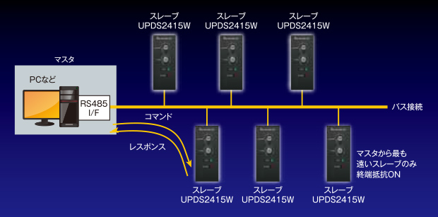
RS-485 available for external light control (i.e. master-slave scheme).
Multi-dropped connection with up to 31 units.
Individual status management of controllers allowed.
Multi-CH control allows a wide range of applications.
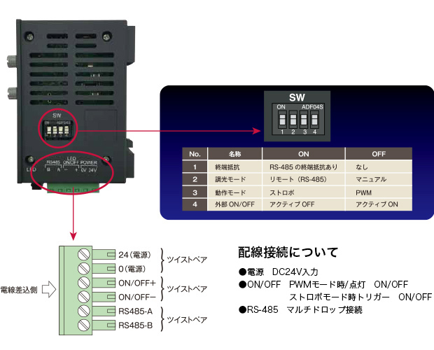
A terminal separate from RS-485 is used for external ON/OFF control.
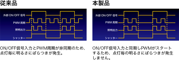
I/O control and reversal of polarity are allowed. ON/OFF signals and PWM are synchronized to reduce brightness fluctuation. Response speed is less than 5 μsec (can be up to 15 μsec during communication).
A DIP switch is used to switch between PWM and flash light emission.
Flash light emission can be adjusted at 10 μsec intervals between 10-2550 μsec.
Trigger response speed/response speed is less than 5 μsec (can be up to 15 μsec during communication).
(*No overdrive is used for flash lighting.)
●Manual selection of PWM/flash light emission
●Remote selection of PWM/flash light emission by RS-485
●Reversal of light emission polarity
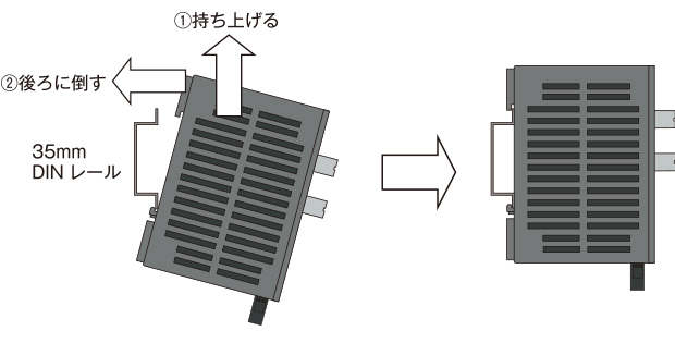
(1) Fit the DIN rail mounting section on the back of the enclosure with the lower edge of a DIN rail, and lift up the enclosure.
(2) Press the enclosure against the DIN rail and hook it on the rail’s upper edge.
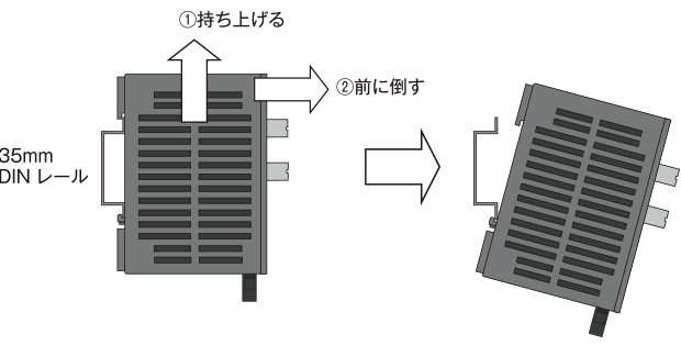
(1) Lift up the enclosure.
(2) Pull and tilt the enclosure as illustrated below. When the upper notch of the enclosure comes off the rail’s upper edge, the entire enclosure can be removed from the DIN rail.
| Type | UPDS2415W-1 / UPDS2415W-1DCJ | |
|---|---|---|
| Light emission system | PMW/flash at constant voltage | |
| No. of LED light connection | 1 | |
| LED light output | 24VDC, 0.62A or below (15W max.) | |
| LED light connector | Main unit side: SMP-03V-BC (JST, 3-pin) Light side: SMR-03V-B (JST, 3-pin) |
|
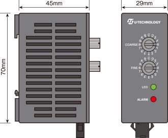
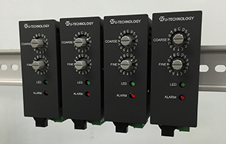
| Mounting method | 35 mm DIN rail mounting | |
| Connectors | Main unit side: XW4A-06B1-H1 (Omron, 6-pin) Cable side: XW4B-06B1-H1 (Omron, 6-pin) Compatible electric cables: AWG16-28 stranded cables |
|
| Input power supply | 24VDC (23-25V), 1A or below *When using a DC jack, use a positive-ground plug that is 2.1 mm in I.D., 5.5 mm in O.D. and 9-10 mm in insert length. |
|
| Input overcurrent protection | Polyswitch (restored at power OFF) | |
| Operative temperature and humidity range | 0~40℃, 20-85% RH (non condensing) | |
| Cooling system | Natural air-cooling | |
| Environmental control | RoHS-compliant | |
| Outside dimensions | 70x45x29 mm (excluding protrusions and DIN rail fittings) | |
| Weight | Below 0.1kg | |
| PWM system | Light emission system | Constant voltage PWM, PWM frequency: about 750 kHz |
| Light control system | Manual/Remote (RS-485) | |
| Light control range | Manual: 0-255 by front knob (light intensity not varying between 1-10) Remote: 0-255 by RS485 (light intensity not varying between 1-10) |
|
| Light ON/OFF | External ON/OFF signals (polarity reversal allowed) | |
| Flash system | Light emission system | Light is emitted for a certain period of time triggered by external ON/OFF signals |
| Light emission time setup | Manual/Remote (RS-485) | |
| Light emission time range | 0-2550μ (at 10 μsec intervals) | |
| Alarm detection | Output overcurrent (operation halted; restored at power OFF) Communication failure (operation continued; automatically restored after several seconds) |
|
| Alarm output | Output overcurrent: Alarm indicator ON and lighting OFF Communication failure: Alarm indicator ON for several seconds and lighting remaining ON |
|
| Accessories | Instruction manual, connectors (XW4B-06B1-H1) | |