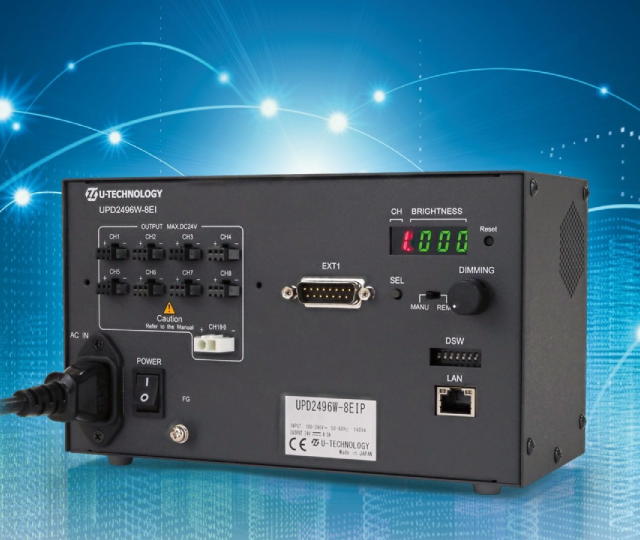
UPD2496W-8EIP
8-channel, 96W high-capacity power supplyBuilt-in programming function
High-resolution dimming with 1,000 levels
download manual

検索
| Item | Contents | |
|---|---|---|
| Name | Ethernet support digital pulse control power supply | |
| Model number | UPD2496W-8EIP | |
| control channels | 8ch | |
|
Output for LED lighting device ※1 |
24VDC 96W(Max.) | |
| CH1~CH8 | 72W(max.) Output Connecter:SMP03V-BC (JST) | |
| CH1 (H) | 96W(max.) Output Connecter:ELR-02V (JST) | |
| Control method | Constant voltage PWM system / Strobe system ※2 | |
| PWM system | Output Voltage | 24VDC typ. (fixed) |
| PWM Frequency | Approx. 160kHz | |
| Dimming Steps | 1000 step | |
| Strobe system | Output voltage | 24VDC(Fixed) ※3 |
| Lighting activation | Trigger signal to the main unit | |
| Lighting delay | 5μsec typ. | |
| Lighting time |
10μsec~999μsec (1μsec step) 10μsec~9990μsec (10μsec step) 100μsec~99.9ms (100μsec step) ※2 |
|
| Lighting regularity |
None (Trigger signals are not accepted while the light is being emitted.) |
|
| Trigger signal pulse | Pulse width:More than 20μsec, less than lighting frequency | |
| Trigger polar signal | Polarity reversible (All channels at once) ※2 | |
| Installation method | Equipped to the machine fixing by M3 screw or DIN rail | |
| Input voltage | AC100~240V ±10% | |
| Power consumption | 140VA typ. | |
| Inrush current(100V/200V) | 15A/30A typ. (Cold start) | |
| Power supply cord | AC power code with grounded IEC C14 Type | |
|
Protection from overcurrent |
Fuse(3.15A) ※4 | |
| Operating environment | Indoor use only | |
| Temperature | 0~40℃ | |
| Humidity | 30~85%RH (non-condensing) | |
| Altitude | 2000m (Max) | |
| Pollution degree | Level 2 | |
| Protection class | Class Ⅰ | |
| Installation category | Ⅱ | |
|
Storage Temperature/Humidity |
-15~65℃ / 20~85%RH (non-condensing) | |
| Cooling method | Forced cooling (side intake/side exhaust) | |
| Environmental regulation | RoHS | |
| CE Marking |
EMC directive (EN61000-6-2, EN61000-6-4) Low voltage directive(EN61010-1) |
|
| Dimming method | Manual mode | Dial and push buttons indicated by 7 segment LED |
| Remoto mode | Ethernet (10BASE-T/100BASE-TX) | |
| Programming mode | 16 sequence、8 pattern | |
|
External control connector |
Ethernet | RJ45 ※5 |
|
ON/OFF、 Alarm output |
D-sub 15P(male) ※6 | |
| LED ON/OFF | Method | By signal from outer device (Polarity reversible) |
| Alarm | Detected items | Output overcurrent、Fan abnormality |
| Display / Output | Alarm shown on the front panel, all LED turn off. | |
| Alarm signal will be output from the external control connector | ||
|
Checking the cause of alarm by sending alarm check command ※7 |
||
| Deactivation method | Turing off the power | |
| Deactivation command ※8 | ||
|
Ethernet communication setting |
IP Address | Fixed IP(Default setting:192.168.1.10/24 Port:50001) |
|
Communication method |
TCP/IP | |
| Setting | TCP server ※9 | |
|
Number of client connection |
1 | |
| Initializing | Reset operation returns to the initial value | |
| Dimension |
W208mm x H120mm x D95mm (exclude robber foots and projected parts) ※10 |
|
| Weight | approx.1.5kg | |
※1 The total power of the connected lights must not exceed 96W. Also, the power output from CH1 to CH8 normal output ports alone must not exceed 72W.
※2 In manual mode, switching is done using a dip switch (DSW). In remote mode, settings are made using commands.
※3 The over drive lighting is not functional.
※4 It is equipped on the witching power supply.
※5 The ethernet connector is not enclosed in the package.
※6 D-sub connector is not attached.
※7 The Automatic Alarming Function is not equipped.
※8 Deactivation by command is allowed only at the ethernet operation.
※9 The control side(PC, etc) should be TCP Client.
※10 Please see the outer dimension.
※11 The specification might be changed without notice as adding function or functional improvement.